The display element is the link between the traffic stream on the vs | plus side and the signal groups or digital outputs on the control unit level. There must be a display element in vs | plus for each signal that is to be switched on the road.
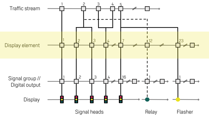
Figure 26: Display elements between traffic streams and signal groups
In addition to a unique name and ID no., display elements must have a link to an output element on the control unit (VTU1). Each output element can only be assigned to one display element. vs | plus recognises the output elements:
- Signal group (SG)
- Digital output relay (DO)
- Digital output flasher (FL)
The subdivision of the digital outputs DO and FL is due to historical reasons. New control units only have one type of digital output. DO is used in most cases today. Before supplying the control unit, clarify with the manufacturer which type it supports. The remaining properties can be set as required.
|
Display |
Identifier |
Values |
Description |
|
ID No |
ID number |
|
For identification purposes, a unique number must be assigned to each display element. It is mandatory to assign the properties type and channel number of the output element to each defined display element. |
|
|
1 .. 96 |
Depending on the vs | plus version. |
|
|
Name |
Name of the display element |
|
Must be unique. |
|
DE_Type |
Display element type |
|
The calculation of a phase transition takes place at the level of the display elements. In order for vs | plus to issue the correct switching commands to the corresponding switching elements of a control unit, the corresponding type of switching element must be assigned to each display element. |
|
|
|||
|
|
|||
|
|
SG |
Signal group consisting of 1s to 3 chambers is monitored. |
|
|
|
DO |
Digital output, is switched on and off, is not monitored. |
|
|
|
FL |
Digital output is identical to DO, but flashes when switched on. Is not monitored. |
|
|
Signal group |
Reference to a signal group |
|
A signal (control actuator), such as signal group, digital output, etc., must be assigned to each display element. With the type of SG, this assignment is made with a relationship to the signals defined in the node module Control Units > Topology > Signal Groups, Definition for the present intersection. I.e., the assigned signal group can be selected from the existing list. The associated channel number is then automatically displayed. |
|
|
List |
Signal group from the basic data |
|
|
DE_chan |
Channel number |
|
The channel number of the assigned signal (control actuator) is the address with which the switching element is addressed in the control unit. The channel number must be assigned. With type SG, the channel number is entered automatically. It is known by selecting a signal group from the unit topology. The digital outputs are not listed in the device topology. The channel numbers must be entered according to the specifications of the device manufacturer. |
|
|
1 .. 96 |
Channel number of the signal group or digital output |
|
|
DE_Master |
Master display element if dependent |
|
The master display element defines which display element is decisive for the switch-off conditions that must not be exceeded. A hazard flasher controlled by the AND-conditional assignment to an IT and a pedestrian can have different offset end values with respect to the IT indicator element and the FG indicator element. In order to prevent the protection indicator from still being active when the IT indicator element is already showing red, the IT indicator element is assigned to the indicator as the master indicator element. This ensures that the protection flasher is never active longer than defined by the conditions IT display element-protection flasher. |
|
|
List |
Existing display elements |
|
|
DE_Opt |
Red optimisation |
|
When calculating the phase transition, the display element with optimization is optimally considered in the red optimization. This means that these display elements get as much green in the phase transition as possible due to the intermediate and offset times. On the other hand, immediately OFF is not optimized. This means that the display elements are switched off immediately (e.g., immediate closing of a tram after sign-off). The intermediate times to the display elements switching on in the phase transition can thus be greater than required. |
|
|
|||
|
|
Optimisation |
The display element is left on green as long as possible. |
|
|
|
immediately OFF |
The display element is switched off immediately |